Op-Amps and Voltage Comparators
By the end of this note you will know what an op-amp does, why its two input pins behave the way they do, and which of the classic circuits to reach for when a sensor’s signal is too weak for the microcontroller to measure. I wrote it after the two rules below finally clicked for me: a whole pile of circuits stopped looking like magic.
The two rules that explain almost everything
Almost every op-amp circuit you will ever read is one of these two rules used in a particular way, so they are worth getting straight first.
Virtual open. The two input pins take almost no current. In every calculation below you can pretend they take none at all, and treat them as if nothing were connected to them. That is what the name means: an input that is open, but not really.
Virtual short. Wire the output back to the input marked - and you have made a feedback loop, which just means part of the output is fed back to the input. Inside that loop the op-amp drives its output until the two input pins sit at the same voltage. Nothing joins the pins; the op-amp forces them together. Every gain calculation below starts here.
Two more things that decide whether it works
Output saturation. The output cannot go past the supply voltage. Ask for a bigger swing than the supply allows and the output simply stops at its limit and clips: below that limit it copies the input, above it the shape is gone.
Voltage follower. Set the gain to exactly 1 and the output copies the input voltage, but it can now drive a heavy load. You put one between a weak sensor and the next stage, so that the sensor is not dragged down by whatever comes after it.
The amplifier that barely touches the signal
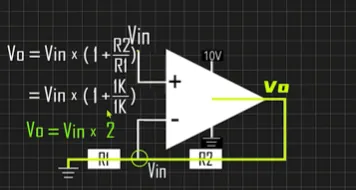
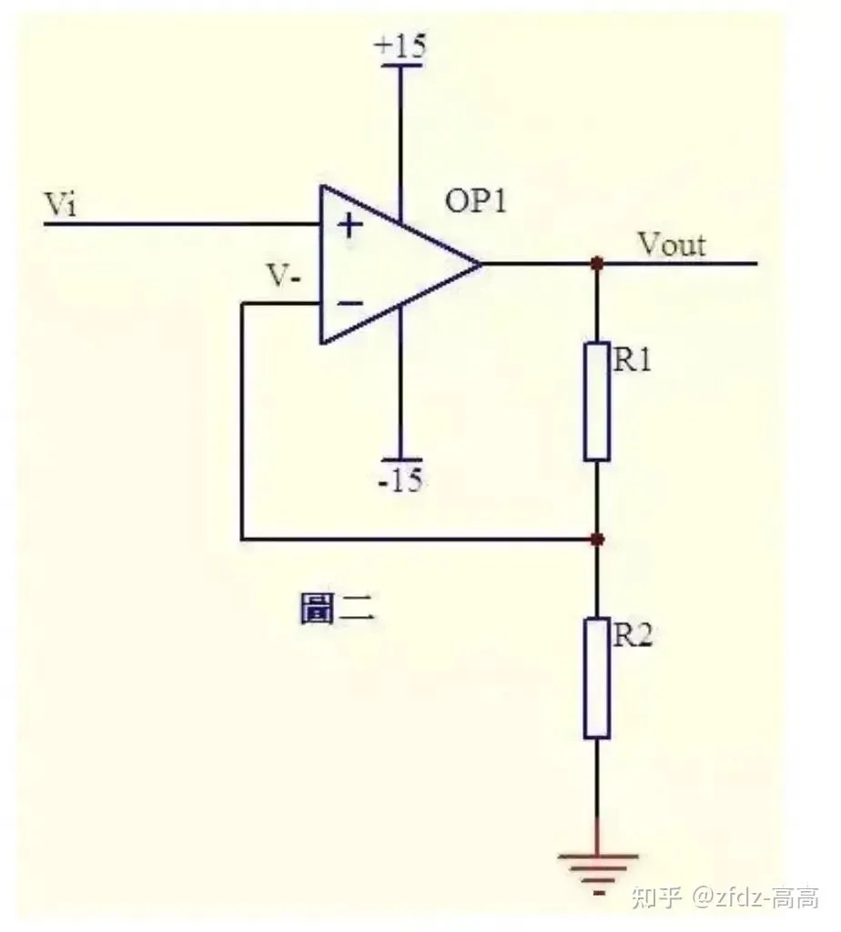
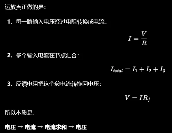
Use this one when the signal comes from something weak, like a sensor. The signal goes into the + input, which draws almost no current, so the sensor hardly notices that anything is there. Two resistors set how much bigger the output gets: Rf runs from the output back to the - input, and Rg runs from the - input to ground. The output rises until the voltage at the - input matches the + input.
Formula: Vout = Vin × (1 + Rf/Rg)
Read it as: the output is the input multiplied by one plus the ratio of the two resistors. Make Rf equal to Rg and the gain is 2. Make Rf nine times Rg and the gain is 10. Because of the 1 in the formula, the gain can never drop below 1, so this circuit only ever makes a signal bigger.
The amplifier that turns the signal upside down
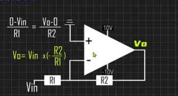
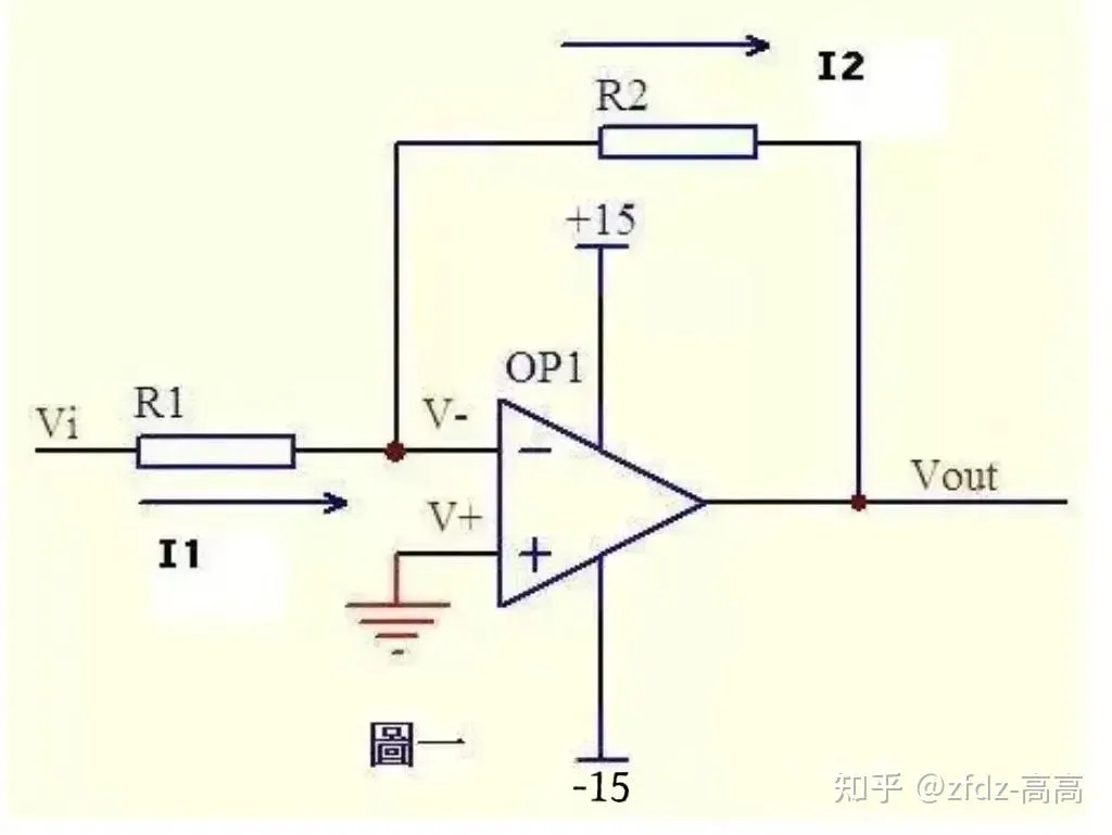
Use this one when you need to add signals together, or to turn a current into a voltage. The signal goes into the - input and the + input goes to ground, which means it moves the opposite way: up in, down out. The trade-off is that the - input pulls current out of the source, so it suits signals that can supply it. Rin sits between the signal and the - input, and Rf sits between the - input and the output.
Formula: Vout = (-R2/R1) × Vi
The minus sign means the output is upside down, and the size of the gain is Rf divided by Rin. That gain can also be smaller than 1, so this circuit can make a signal smaller as well as bigger.
Because the + input sits at ground, the op-amp holds the - input at ground too, even though nothing connects it there. That point is called a virtual ground, and it is what lets several input currents add up in one place.
Which one do I need?
| Property | Non-Inverting | Inverting |
|---|---|---|
| Input impedance | Extremely high (MΩ) | Equals Rin (kΩ) |
| Gain | 1+Rf/Rg, ≥1 | −Rf/Rin, can be <1 |
| Output phase | Same as input | Inverted |
| Virtual ground | No | Yes, at inverting input |
| Typical use | High-Z buffer, sensors | Audio mix, inversion, I-V |
The row that decides most real choices is input impedance, which is simply how much the circuit loads whatever feeds it. The non-inverting input draws almost nothing, so it is safe in front of a weak sensor. The inverting input looks like Rin to the source and pulls current through it, which is exactly what you want when you are adding currents together, and exactly what you do not want from a high-impedance sensor.
Circuits you already own that use it
A kitchen scale or a pressure sensor puts out a tiny difference between two wires, and the op-amp turns that into a voltage the ADC can read (the ADC is the part of the microcontroller that measures a voltage). The range has to be chosen so that loud signals do not clip. A thermocouple puts out even less, and there the amplified signal is used twice: once for the display, once to switch a relay when it passes a set temperature. A PIR motion sensor puts out a small changing voltage when something warm moves, and the amplifier filters it before a comparator (a part that only answers yes or no) decides whether to switch a light. Motor current is measured as a small voltage across a resistor in the motor’s path, then amplified so that the microcontroller can cut the power when it climbs. In audio, a microphone’s signal is amplified and filtered before it reaches a loudspeaker amplifier or an ADC.
Circuits that use the inverting one
Audio mixers are the classic case: every channel gets its own input resistor, all of them meet at the same virtual ground, and the currents add up there. That is why the channels do not interfere with each other. The same stage fixes a sensor that outputs the wrong way round: some sensors give a lower voltage as the pressure rises, and one inverting stage turns that back the right way. Take Rin out and feed a current straight into the - input, and the same circuit converts current into voltage, which is how almost every photodiode detector works (a photodiode is a light sensor that outputs current). Put an inverting and a non-inverting stage together and you get a differential amplifier, the stage industrial sensors use when the signal is the difference between two wires.
What bites you when you build it
An ordinary op-amp such as the LM358 cannot swing its output all the way to the supply voltage. On a 5 V supply it stops around 3.5 V, and the same limit applies to the inputs: they work from ground up to about 3.5 V. Put 6 V on an input and you are above the supply itself, and the part misbehaves. With a 3.3 V ADC that matters, because the op-amp can drive past the ADC’s full scale: it is the ADC, not the op-amp, that sets the top of what you can measure. If you need the full swing, buy a rail-to-rail op-amp, one whose output can reach both supply rails.
Two things are easy to forget. The input pins still draw a little current, and that current has to go somewhere: give each input a path to ground, either through a resistor or through the source itself, or the input voltage drifts and the output drifts with it. And put a 0.1 μF capacitor from each supply pin to ground, right at the chip. Do not skip that one.
If the job is really a yes/no decision, use a comparator, and give it a little hysteresis: one resistor from the output back to the + input creates a small dead zone between switching on and switching off. Without it, the output chatters whenever the input sits near the threshold, and any circuit comparing a slow or noisy signal needs that dead zone.
The classic circuits, and what each one is for
I worked these out by hand while I was learning them. Here is what each one is for and what it does to the signal, without the algebra.
Adding two voltages (inverting input)
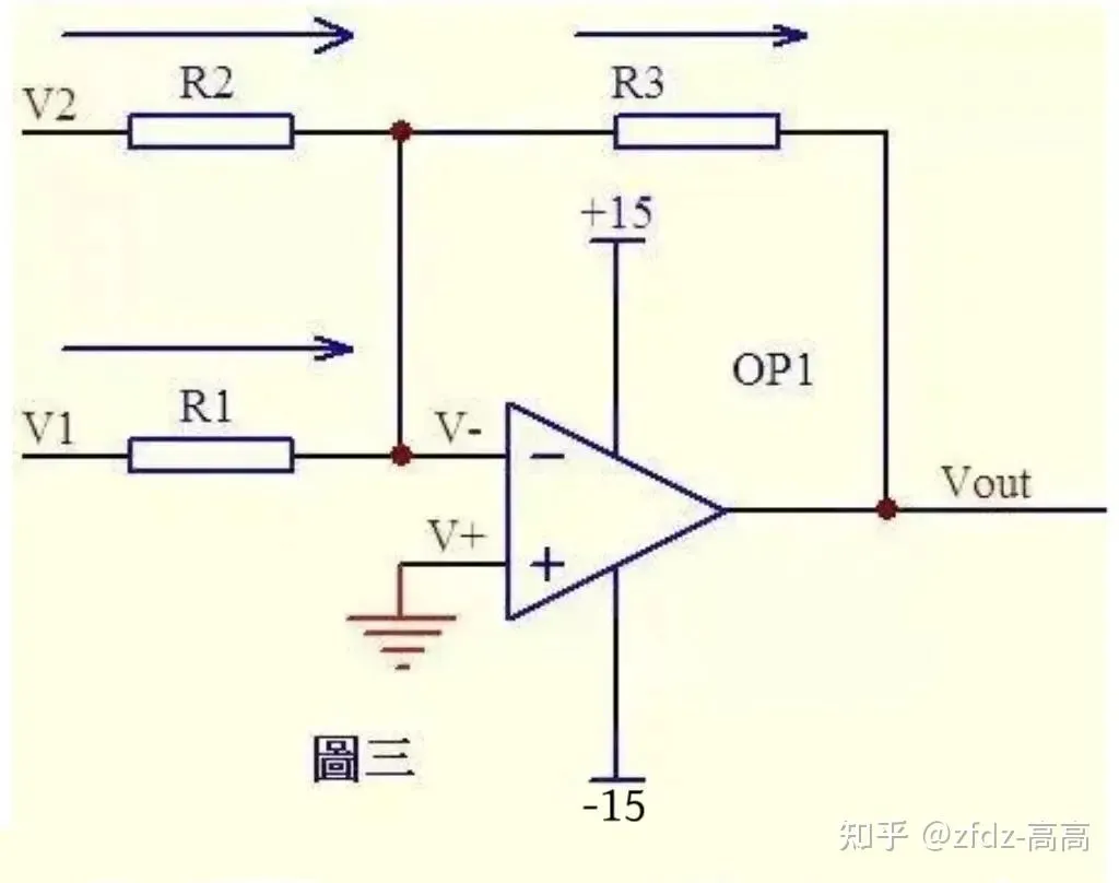
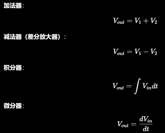
Both inputs go through their own resistor into the - input, which sits at the virtual ground. Because that point cannot move, the currents from the two inputs add up there. With three equal resistors the output is the sum of the two inputs, inverted: the size is right, the sign is upside down.
Adding two voltages (non-inverting input)
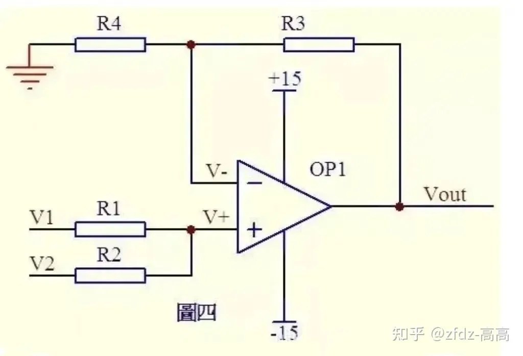
The same sum, built the other way round. The two inputs meet at the + input through R1 and R2, and R3 and R4 form the feedback divider. With R1 = R2 and R3 = R4, the output is the sum of the two inputs, this time with no inversion.
Subtracting one voltage from another
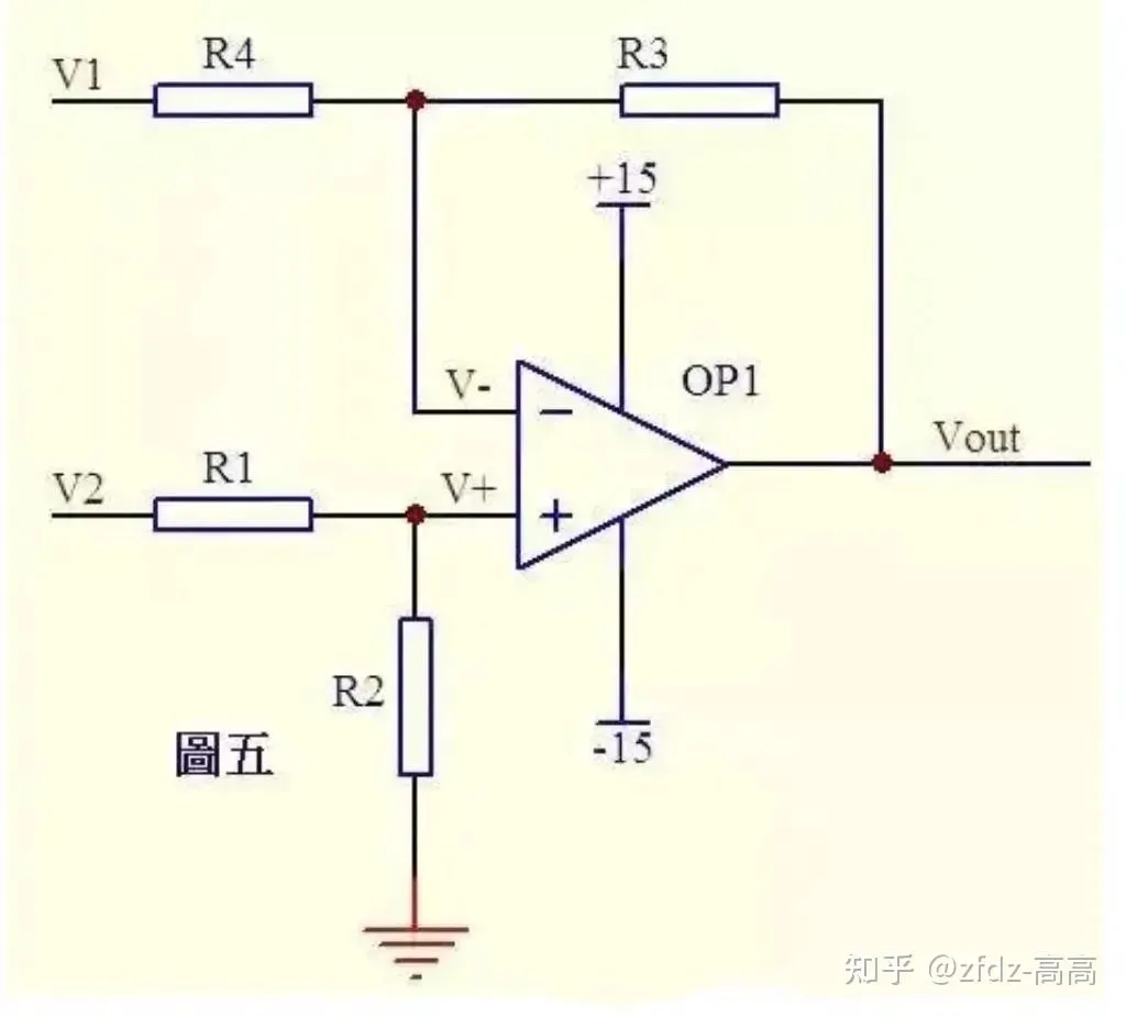
Each input gets a resistor to one of the op-amp inputs, and the feedback resistors are matched in pairs. Whichever input reaches the + pin is the one you keep, and the input on the - side is taken away from it. With matching resistors the output is exactly that difference.
Adding up the input over time (integrator)
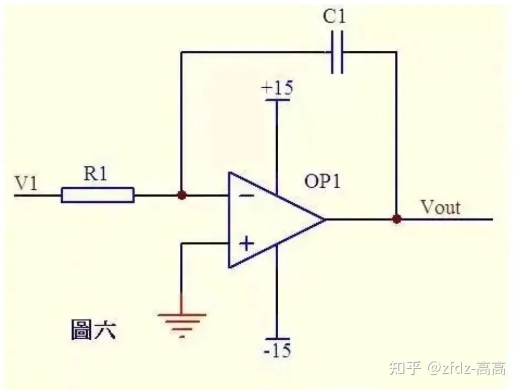
Swap the feedback resistor for a capacitor and the circuit does something different: it adds up whatever comes in. Hold the input steady and the output keeps moving, like a stopwatch you never stop. A constant input makes the output ramp in a straight line, and it ramps until the output reaches the supply rail and stops there.
Reacting to how fast the input changes (differentiator)
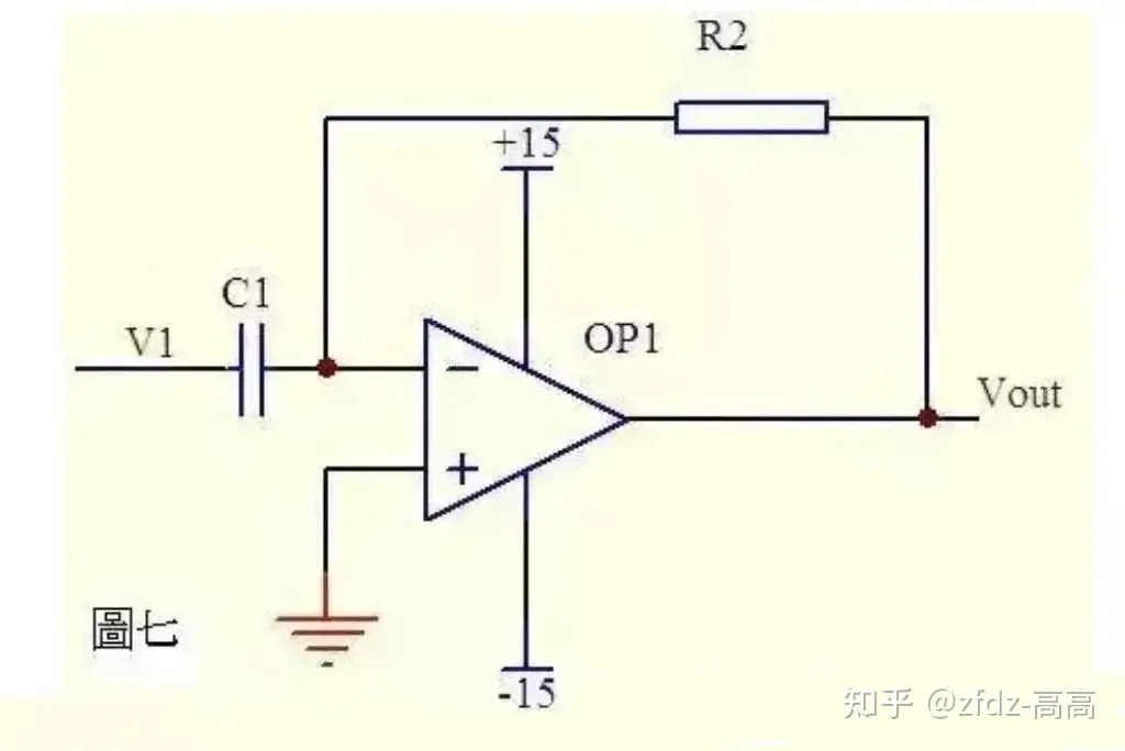
The mirror image: a capacitor at the input and a resistor in the feedback. This one reacts to change, not to level. Hold the input steady and the output sits at zero; make the input jump and you get a spike in the opposite direction.
Reading the difference between two wires (differential amplifier)
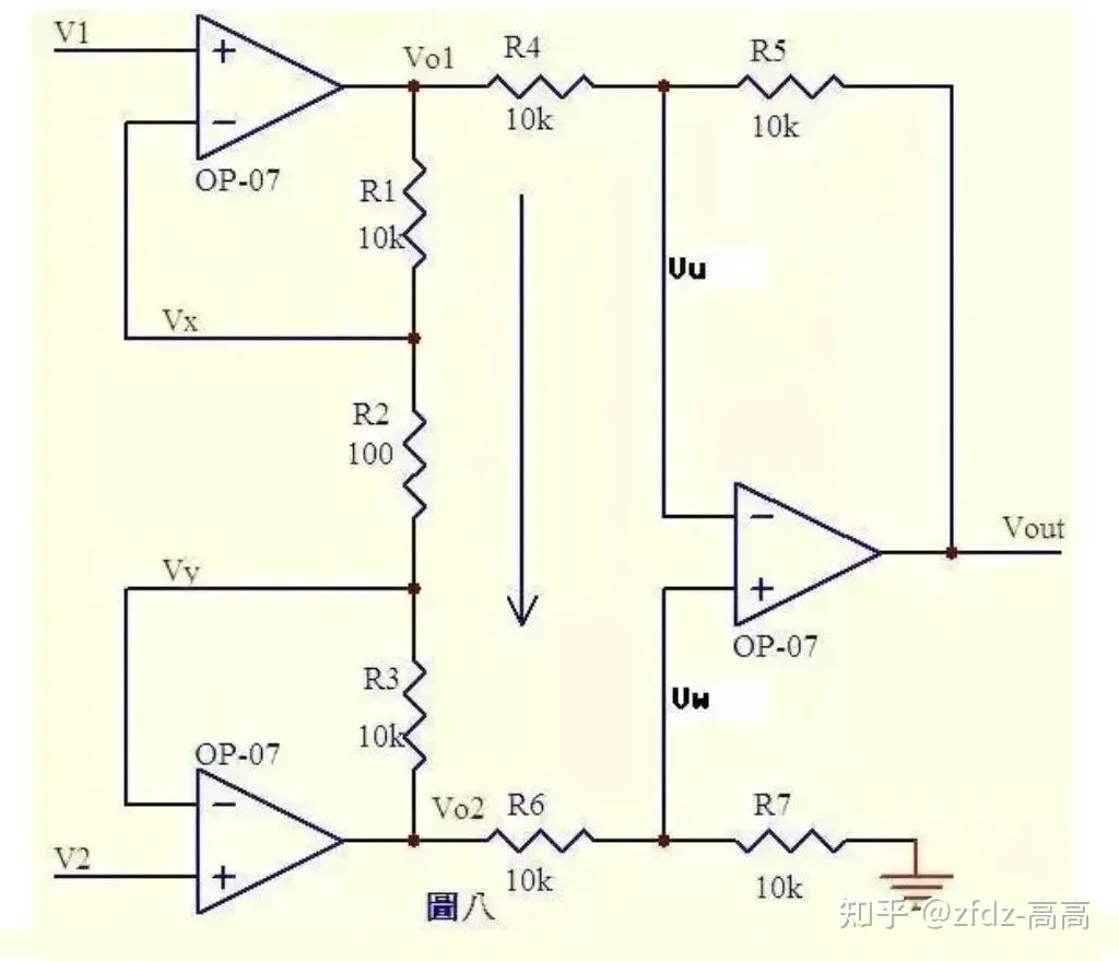
This is the circuit for a signal that lives as the difference between two wires. The first stage measures that difference across the middle resistor, and the chain of resistors around it sets how much the difference is multiplied. A second stage subtracts one side from the other, so you get a single output. Anything the two wires pick up equally cancels out and is not amplified.
Reading a 4~20mA sensor current
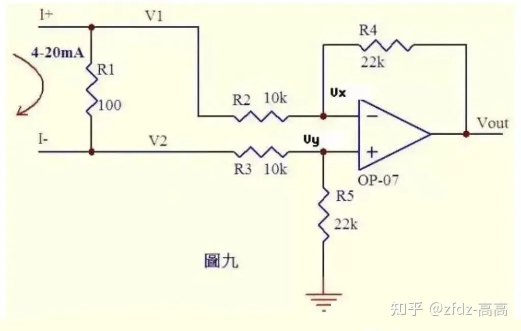
Some industrial transmitters send a current rather than a voltage: 4 mA at the bottom of their range and 20 mA at the top, and controllers often accept a 020mA or 420mA current. Send that current through a 100Ω resistor and it becomes 0.42V. The amplifier multiplies that by 2.2, set by the 22k and 10k resistors, so the ADC sees 0.884.4V. The output comes out negative; turn the current round and it is positive.
Making a current from a voltage
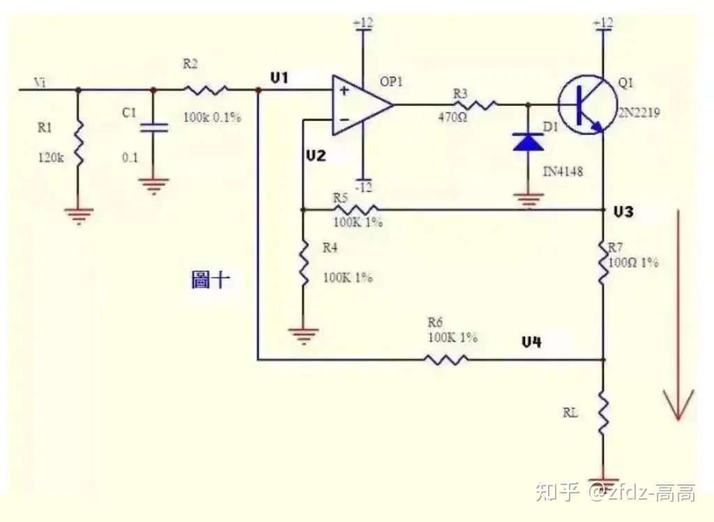
The reverse trick: put a voltage in and take a current out. Here the feedback path runs through a transistor instead of going straight back through a resistor. That does not turn the circuit into a comparator: as long as the transistor is in its active region, the two rules still hold. The current through R7 is set by the input voltage divided by the value of R7, and as long as the load is much smaller than the 100kΩ resistor at the output, almost all of that current goes through the load.
Reading a PT100 temperature sensor
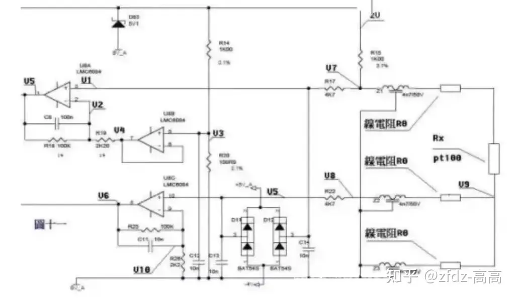
A PT100 is a temperature sensor: a resistor whose resistance changes with temperature, which you then look up in a table to get the temperature in degrees. Three wires go to it, all of the same material and the same length. Two of them carry the current, and the resistance of the cable itself sits in series with the sensor, so it adds to the reading: a long cable looks like extra temperature.
The circuit gets around that by measuring the cable’s own voltage drop on the third wire. The first amplifier turns the sensor resistance into a voltage, and a second amplifier measures the cable resistance on its own. Two measurements, two unknowns, so you can work out the sensor resistance alone and look the temperature up. That second amplifier has to be wired to the cable-drop point and not to the output of the first one: if it simply copied the first amplifier, both readings would carry the same unknown and you could not separate them.
Why is it called “operational”?
The name comes from the days of analog computers, when these circuits really did the arithmetic: adding, subtracting, integrating. It stuck.
Op-amp or comparator: which do I need?
A comparator looks almost the same as an op-amp and does a different job. It does not try to stay linear: it compares its two inputs and answers with a single bit, high or low. Some of them cannot pull their output high at all and need a resistor to the supply to do it.
Op-amps (like LM358) are built to stay in the linear region. With feedback they keep both inputs equal, and the output follows the input continuously. Their job is amplification, which means the shape of the output has to match the shape of the input: take a 0.2V photodiode signal up to 2V and the waveform comes out intact. You can use one open-loop as a comparator in a pinch, but that is not what it is made for.
Comparators (like LM393) are built to switch. They deliberately let the two inputs diverge, and the output slams to one rail or the other, so there are only two states. Their job is decisions: set a 2.5V threshold and the output changes the moment it is crossed.
My rule of thumb:
- Need to read a continuous analog value (temperature curve, light level, pressure waveform) → use an op-amp for buffering, amplification, and filtering, then feed the ADC.
- Need to make a binary decision (temp threshold reached, motion detected, battery low) → use a comparator for a clean HIGH/LOW output or interrupt trigger.