Power Supply Design: Three Questions I Ask First
A circuit almost never runs on the voltage you have. It runs on voltages you have to make, and only two families of part do that: the linear kind and the switching kind. By the end you will know which one to pick, how much heat each makes, and how a lithium cell gets charged safely.
- How big is the gap between the voltage going in and the voltage I need? More than about 3V and 0.3A, and the linear kind is out.
- Will this part of the circuit mind electrical noise? Radio modules and precision analog parts do.
- How much room is there, and how hot can it get? A small sealed box has nowhere to put the heat.
These three questions have saved me a lot of rework.
Power Architecture: It’s an Energy Distribution System
A power supply is a delivery system: every part needs a certain voltage, current and quiet, at its own pins.
Power Systems Are Multi-Stage Conversion Chains
A product usually moves the power through several stages:
Input (USB/Battery) → Protection (fuse, reverse-polarity) → Charge management → Battery → DC/DC conversion → Multiple voltage rails → MCU/Sensors/LEDs/MotorsDifferent parts of the same board want different voltages:
| Module | Typical Voltage |
|---|---|
| MCU | 3.3V |
| Arduino | 5V |
| Sensors | 1.8~3.3V |
| LEDs | 2~3V |
| High-power loads | 12V/24V |
So one product often has 5V, 3.3V and 1.8V rails side by side. A rail is simply one of those supply voltages.
Every stage in that chain loses some of the power it passes on, and a sensitive part may need extra filtering on its own supply.
A fuse has four ratings: current, voltage, the fault current it can break, and how fast it blows. On a battery the third one matters most, because a lithium battery pushes an enormous current into a short circuit and the fuse has to cut that off without bursting. One example: a Class T fuse breaks 20kA at 125V DC.
LDO Linear Regulators: Clean and Simple, But They Get Hot
An LDO (low drop-out) is a linear regulator that still works when the input is only slightly above the output. It behaves like an automatic resistor: it drops the leftover voltage to keep the output steady, and that voltage turns into heat:
P_loss = (Vin - Vout) × IIn words: the loss is the voltage dropped across the part times the current through it. Drop 5.5V to 5V at 1A and 0.5W is lost, about 91% efficient. Drop 12V to 5V at 1A and 7W is lost, only 42% efficient.
The good side: almost no circuit to build, cheap, quiet and steady.
I reach for an LDO when:
- A lithium cell sits at 3.6V and the microcontroller needs 3.3V, so only 0.3V is left over.
- The part being fed cares about noise, like an audio amplifier or an analog-to-digital converter.
I would not use one to drop 12V to 5V at high current; the heatsink gets silly.
Practical lessons:
- The chip’s internal temperature is the room temperature plus the loss times the thermal resistance of the package. Keep it under the datasheet limit.
Buck Switching Converters: Efficient, But With Ripple
A Buck does the opposite: it never burns the extra voltage off. It chops the input on and off thousands of times a second and then smooths it back into a steady output. A MOSFET, a switch worked by voltage rather than current, does the chopping; an inductor and a capacitor smooth it out. Efficiency is usually 85% to 97%.
The price is a small wobble on the output at the switching speed, called ripple. You also need more parts: an inductor, a diode that gives the coil’s current somewhere to go when the switch opens, and capacitors on the input and the output.
Ripple happens at battery scale too, for a different reason. An inverter pulls its current in pulses at twice the grid frequency (100Hz), and the resistance of the battery cable turns those pulses into a voltage wobble on the DC bus. Victron’s guide puts the alarm level at 2.25V RMS on a 24V system.
So my default is a Buck whenever the drop is more than about 3V and the current more than about 0.3A: 12V down to 5V, or a battery down to something that draws a lot. The LM2596 module is the one I keep on the bench: cheap, and you set the output with a small screw.
Lessons learned the hard way:
- Pick the inductor for the current it will carry. Past its limit, called saturation, it stops behaving like a coil and behaves like a plain wire, so the MOSFET can fail.
- Keep the copper track where the MOSFET meets the inductor short and wide; that point switches fast and sprays interference.
Boost and Buck-Boost
A Boost goes the other way: it makes a higher voltage out of a lower one, so one lithium cell at 3.7V can feed a 5V or 12V load. It stores energy in the inductor while the switch is on, then lets it out in series with the input when the switch opens, so the two voltages add. A Buck-Boost covers the case where the input starts above the output and ends up below: a lithium cell is 4.2V full and 2.7V nearly empty, so it switches modes by itself to hold 3.3V.
Practical notes:
- A Boost can pull a big surge of current when it starts, so most ramp up gently. That is called soft-start.
- Do not short the output of a Boost; plan the protection before you build it.
Battery Charging and Protection: Both Are Mandatory
You cannot charge a lithium cell by putting 5V straight onto it. The current has to be limited and the voltage watched, and a dedicated chip does that.
- TP4056: a small charging chip. It charges at a steady current until the cell reaches 4.2V, then holds that voltage, and turns the leftover voltage into heat. The big pad underneath carries that heat into the board, so pour copper under it and stitch it with vias.
- Protection board (a DW01 chip and an 8205A pair of switches): it watches the cell’s voltage and current and cuts the connection if the voltage climbs to about 4.30V, falls to about 2.40V, the current gets too high, or the output is shorted.
The complete chain for one lithium cell:
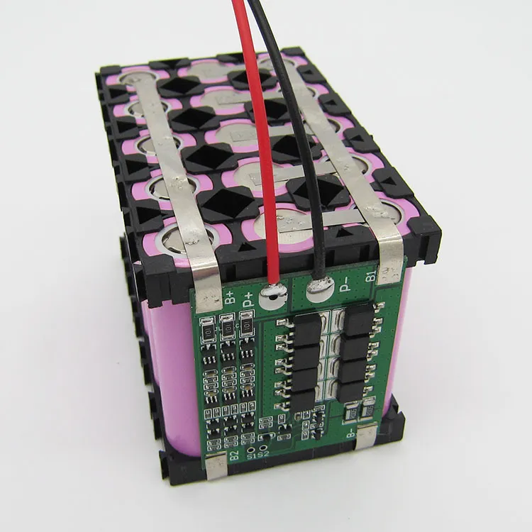
Most cells come with the protection board already built in, as one unit.
Input 5V → TP4056 → [Li-ion cell + Protection board (integrated)] → Buck/Boost → Various loads
↑____Charging____↑ ↑____Discharging____↑- While charging, the TP4056 controls the current going in and the protection board watches the voltage.
- While discharging, the current leaves the cell through the protection board, which watches for a voltage that has dropped too low, or for a short.
When you set the charging current, remember where it comes from: your USB port. The usual 1A is too much for a small cell. The protection board has to sit on the cell, not on the main board at the end of two wires. Most TP4056 modules already include the DW01 and the 8205A, so charging and protection come as one board.
Efficiency and Thermal Design: High Efficiency ≠ No Heat
A Buck that is 95% efficient and delivers 50W still turns about 2.6W into heat, which is enough to make the MOSFET noticeably warm.
That heat leaves through the pad under the MOSFET and into the case, and phone chargers and laptop adapters use the case itself as the heatsink.
Check the temperatures, by testing or by simulating, and make sure nothing goes past its limit in the hottest conditions it will ever see.
The Three Questions Revisited, With a Case Study
What Happens With The Same Load?
- LM7805, a linear regulator: 9V in, 5V out to an Arduino. After five minutes the chip is noticeably hot, at about 55.6% efficient.
- LM2596, a Buck module set to 5V with the same load: barely warm, about 92.6% efficient.
For anything that runs on a battery, I would start with a switching supply.
Opening Up An Old Phone Charger
I once took an old phone charger apart and followed the power from the mains plug to the USB socket.
AC 220V → fuse resistor → common-mode choke → bridge rectifier → 400V bulk electrolytic → transformer primary → switching IC → transformer secondary → Schottky rectifier → electrolytic filter → 5V USB outputThe part I find most interesting is the optocoupler, which sits across the barrier between the dangerous mains side and the safe 5V side.
Core Takeaways
The design chain runs energy flow, voltage conversion, the thermal path, then the mechanical integration. This is where electrical engineering and industrial design meet.
FAQ
Why must the protection board be integrated with the battery?
Because it has to sit as close to the cell as possible, usually welded onto the cell’s terminals with nickel strips. Move it to the main board and the current travels through extra wires and connectors instead.
Can I charge a protected battery directly with TP4056?
Yes, that is the normal way. The TP4056 runs the charging and the protection board is the last line of defence.
Why is my Buck circuit still getting hot?
Even one or two watts will push the chip’s internal temperature up if nothing carries the heat away. Check the inductor’s current rating, the board’s copper area, and where the heat goes.
Knowledge Base: Module Reference Cards
Regulator Modules I Keep On The Bench
| Module | Type | Vin | Vout | I_max | Efficiency | Heat | Use Case |
|---|---|---|---|---|---|---|---|
| LM7805 | Linear | 7-25V | 5V | 1.5A (w/ sink) | ≈Vo/Vin | High | Low current, noise-sensitive |
| LM2596 | Buck | 4.5-40V | Adj 1.25-37V | 2-3A | 85-93% | Low | Large voltage drop, efficiency-first |
Charging And Protection In One Board
| Module | Function | Charge Method | Protection | Notes |
|---|---|---|---|---|
| TP4056+Protection | 1S Li-ion charging | Linear, 1A adj | OV, UV, OC, SC | Must pair with protection board |
Further Reading
How Mains Adapters Are Built, By Power Level
Mains adapters come in families by power level: the flyback up to about 100W, the forward, push-pull and bridge circuits above that, and the resonant LLC in modern PC supplies, which reaches 90% to 96%.
Getting Rid Of Ripple
If you want efficiency and a quiet output together, put an LDO after the Buck.
Input DC → Buck → LDO → Load
The Buck takes the big drop, say 12V down to 5.5V, at better than 90% efficiency. The LDO then has only 0.3–0.5V left to drop, so it barely warms up, and it smooths out the wobble.
Pick The Battery First
Work out the voltages the system needs first, then pick the battery: a lithium cell is 3.7V, a NiMH cell 1.2V, and that decides whether you need a Boost or a Buck-Boost.
When It Grows Into A Battery Bank
When this grows into a battery bank, the same questions come back bigger. Victron Wiring Unlimited covers them in detail, and my off-grid solar project leans on it heavily: Home Low-Load Solar Panel Circuit Design