Background
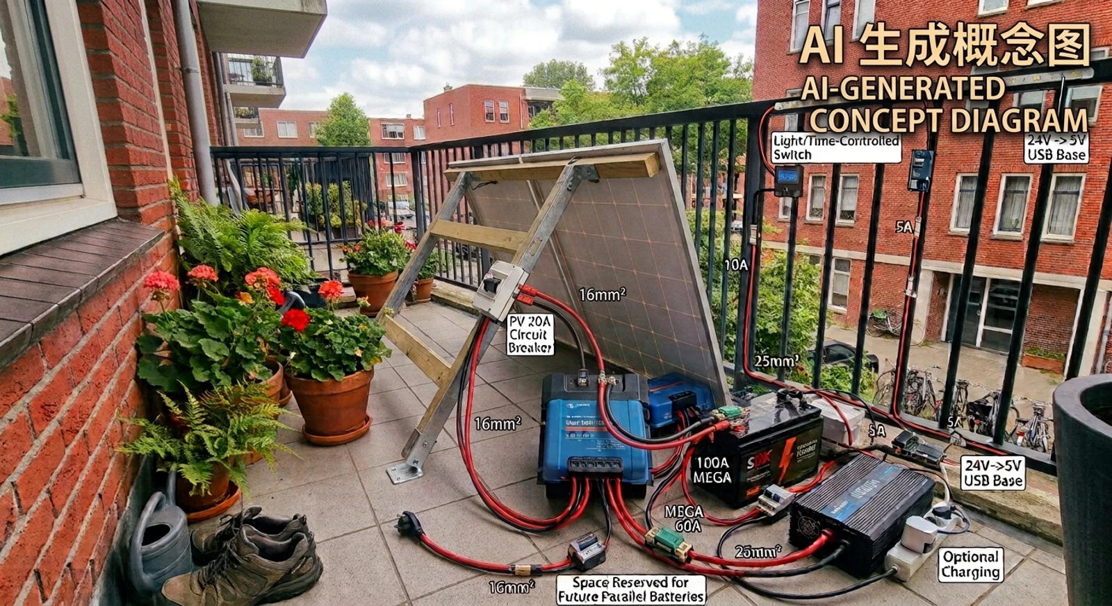
I’m building a solar storage system around low-power flexible panels. In its current form it exists to run LED lighting off-grid. If the system later expands, or needs to feed high-load household devices, the panels upgrade to fixed rooftop modules.
The engineering problem I found most interesting is a voltage-matching constraint: a battery can only be charged when the solar array’s operating voltage sits comfortably above it, and that single rule decides almost everything downstream: panel configuration, battery voltage, controller choice. Everything in this design follows from that rule.
Requirements
| Requirement | Target |
|---|---|
| Night lighting | LED, 50W × 8h = 400Wh per night |
| Storage | 2 × 12V 100Ah LiFePO₄ in series = 24V (~2.5kWh, expandable) |
| Solar | 2 × 300W portable semi-flexible panels (low-power stage; rooftop panels are the future upgrade for high loads) |
| 230V backup | 24V × 100A ≈ 2400W theoretical output (short-time capability, see §04) |
| Sourcing | Solar panels + battery locally; everything else cross-border |
Design Process
01 Research: The Voltage-Matching Constraint
The core rule comes from MPPT charge controllers: they only start charging when the solar array voltage exceeds battery voltage +5V, and they need roughly battery +1V to keep charging. The chosen 300W semi-flexible camping panels run at 20Vmp, too low to charge a 24V battery on their own; in series they give 40Vmp / 50Voc, comfortably above any 12V or 24V threshold, and far under the controller’s 100V ceiling even at −20°C.
The MPPT-to-battery connection uses 16mm² cable, limited by the MPPT’s 16mm² maximum terminal size; ideally 25mm² would be used to leave proper safety margin.
On the market side: 12V packs dominate the Dutch camper/boat market, so the storage side settled on 2 × 12V 100Ah. Wiring rules, fuse placement and charge parameters were verified against Victron’s manuals, the Wiring Unlimited guide and documented DIY builds.
02 System Architecture
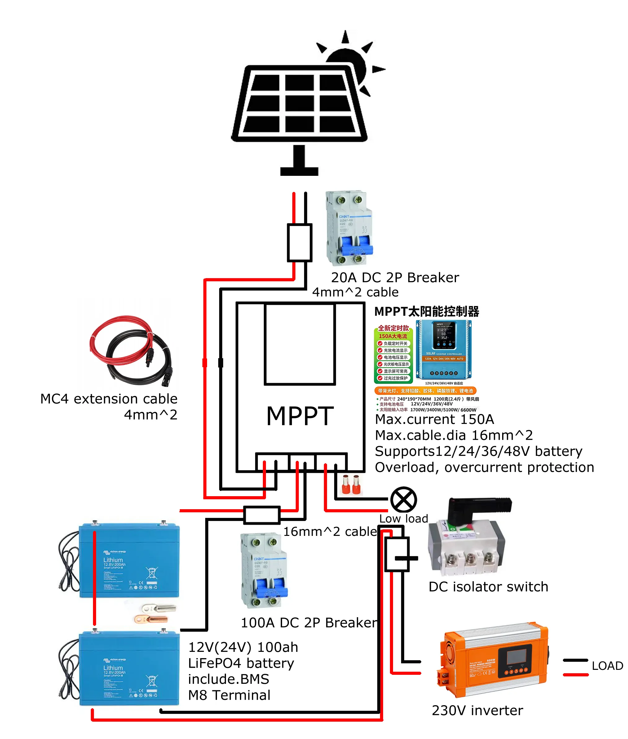
The controller is a single MPPT unit with three terminal groups: PV, BAT and LOAD. Solar lands on PV, the battery reaches BAT through a 2P DC breaker, and the LED lighting hangs off LOAD through its own switch. Anything that draws real current, the inverter above all, comes off the battery instead. The battery is the only bidirectional device in the system, so at any instant its current equals load current minus solar current: it absorbs the surplus or covers the deficit on its own.
The two 12V batteries are wired in series for 24V: this keeps the inverter branch at a 100A-class current (24V × 100A = 2400W theoretical output). Paralleling at 12V would need 200A for the same power, which doubles the copper on that branch and quadruples the heat it sheds. Each battery carries its own built-in BMS.
Voltage Drop Check: the Inverter Branch
The wiring guide’s worked example happens to be almost exactly this system: a 2400W inverter on a 24V battery. Its numbers apply directly. 16mm² copper cable works out to R = ρ × l / A = 1.7 × 10⁻⁸ × 1.5 / (16 × 10⁻⁶) = 1.6mΩ per 1.5m of cable. With the planned battery-to-inverter run of 1–2m (1.5m used here), the full loop, positive plus negative, is 3.2mΩ, and at the inverter’s 100A:
- Voltage drop: V = I × R = 100 × 0.0032 = 0.32V, 1.3% of 24V
- Power lost as cable heat: P = I² × R = 100² × 0.0032 = 32W
The guide advises staying under 2.5% drop (0.6V at 24V), so 16mm² at 1.5m clears the bar. Stretched to 3m the same cable reaches 2.7%, which is exactly where the “ideally 25mm²” note in §01 comes from: 25mm² at 1.5m would drop about 0.2V. The inverter branch is the only run in this system where cable resistance actually matters. The MPPT-to-battery run only carries charge current (600W ÷ ~27V ≈ 22A), and 1m of 16mm² drops about 0.05V there, so the MPPT’s 16mm² terminal limit is a non-issue on that side.
Series vs Parallel: What the Wiring Guide Says
The series decision matches the guide’s advice on large battery banks. It recommends against building big banks from many paralleled 12V strings, capping it at 3–4 parallel strings, because wiring differences plus the small differences in battery internal resistance (typically 3–10mΩ) create imbalance. Current always takes the path of least resistance, so the battery closest to the terminals gets worked harder, discharged harder, charged harder, and fails first. Two batteries in series sidestep that problem. Series brings its own balancing question (those internal resistance differences again), which is handled by each battery’s built-in BMS, with both units charged to full before the first series connection (§05).
03 Key Decisions
| Item | Decision | Why |
|---|---|---|
| Battery | 2 × 12V 100Ah LiFePO₄ in series = 24V (100A BMS each, built-in) | Series keeps the inverter branch at 100A class (24V×100A=2400W); same model & batch; confirm BMS supports series |
| Panels | 2 × 300W semi-flexible in series | Portable-first; series is mandatory for 20V panels; rooftop panels are the future upgrade |
| Controller | MPPT (PV / BAT / LOAD terminals) | Single unit, three terminal groups; BAT terminals take max 16mm² |
| Inverter | Pure-sine inverter (24V input) | 2400W theoretical, short-time |
| Protection | DC-only non-polarized breakers + isolator switch | Breakers sized to cable ampacity; DC-rated only, AC breakers cannot quench DC arcs |
04 Efficiency Estimate: the 230V Chain
Every conversion stage takes a cut. Typical efficiencies at this power level:
| Stage | Typical efficiency |
|---|---|
| MPPT DC-DC conversion | 92–95% |
| LiFePO₄ charge + discharge round trip | ~95% |
| Pure-sine inverter DC→AC | 88–93% |
Multiplying the full chain (panel → battery → inverter → 230V):
0.94 × 0.95 × 0.90 ≈ 80%
Expect roughly 77–84% end-to-end in practice (typically ~80%). For comparison, the LED path skips the inverter entirely (≈90% through MPPT + battery), which is why lighting runs directly on DC and 230V stays a reserve: every kWh pushed through the inverter chain leaves about a fifth behind.
Where the Losses Go: Ripple
The guide points to one more loss mechanism that the efficiency chain doesn’t show: ripple. An inverter draws a fluctuating DC current from the battery at twice the AC frequency (100Hz on a 50Hz grid), and every fluctuation appears as a voltage swing across the cable resistance. The larger the voltage drop, the larger the ripple. On 24V systems Victron alarms above 2.25V RMS (hard alarm at 3.75V) and lists thin or long battery cables as the first cause. With the inverter branch at 1.3% drop, ripple here stays well below the alarm level. The fix list is identical to the voltage-drop fix list: short cables, thick copper, tight connections. Ripple also ages the inverter’s capacitors and eats into battery life, so it is worth rechecking if the branch ever gets longer.
05 Protection & Safety
- PV side: 20A 2P non-polarized DC breaker, doubling as a maintenance isolator; the MPPT-to-battery line runs through a 2P DC breaker (battery isolation). All breakers/switches must be DC-rated and non-polarized; AC breakers cannot quench DC arcs.
- LOAD branches: the LED hangs directly on the LOAD port (via a light/timer switch); the inverter branch runs through a DC isolator switch used for daily on/off, which also kills idle draw.
- Wiring standards: the MPPT uses the common green screw-clamp terminal blocks, paired with pin ferrules (no tinned wire ends, solder creeps); closed copper lugs onto M8 studs (no open lugs); hydraulic crimp; red/black discipline.
- Batteries in series: same model, same batch; confirm the BMS supports series connection; fully charge both before series wiring.
- Commissioning: polarity check before powering anything, battery first and PV second, charge parameters set per the LiFePO₄ 24V spec.
Fuse Selection: Four Criteria
The guide reduces fuse selection to four criteria: current rating, voltage rating, interrupt rating and speed. Two of them deserve attention here:
- Speed: DC circuits with capacitive loads (an inverter charges its input capacitors at power-on) want a slow-blow (T) fuse; a fast fuse will nuisance-trip on inrush.
- Interrupt rating: LiFePO₄ delivers far higher short-circuit currents than lead-acid, and the fuse has to break that fault current without rupturing itself. Typical ratings: MEGA fuses 2.5kA at 70V DC, MRBF 2kA at 58V, NH blade fuses 25kA, Class T 20kA at 125V DC (the 200kA figure often quoted for Class T is its AC rating). The 100A DC breaker on the MPPT-to-battery line needs this checked against the battery’s short-circuit spec before commissioning. For lithium systems the guide calls at least one DC-line fuse or breaker with an adequate interrupt rating a mandatory safety requirement.
06 Cross-Check Against the Wiring Guide
| Check | Guide rule | Status |
|---|---|---|
| Inverter branch drop | max 2.5% at 24V (0.6V) | 1.3% at 1.5m of 16mm² ✓ |
| Battery bank | max 3–4 parallel strings, mind the balance | 2-in-series, BMS balanced ✓ |
| Fuse placement | main fuse near the battery, every consumer fused individually | 100A breaker on the battery line ✓; the inverter branch currently has only the isolator switch, its own fuse is an open item |
| Fuse speed | T (slow) for the inverter’s inrush | verify at purchase |
| Interrupt rating | at least the battery’s max fault current | verify the 100A breaker spec before commissioning |
| Ripple | pre-alarm at 2.25V RMS on 24V | 1.3% drop leaves a large margin ✓ |
BOM Overview
I’m sourcing the solar panels and the battery from Dutch shops (warranty and shipping logic); everything else, MPPT, inverter, breakers, isolator, cables, terminals and accessories, comes from Taobao cross-border. Prices converted at €1 = ¥7.81. The full spec with the wiring list lives in the project folder; this is the condensed version.
| # | Item | Spec | Qty | Est. price | Source |
|---|---|---|---|---|---|
| 1 | Solar panel | 300W semi-flexible, ETFE, MC4 leads | 2 | €150–250/pc | Local / Taobao |
| 2 | MPPT controller | 6-port (PV/BAT/LOAD), BAT terminals max 16mm² | 1 | ≈ €26.9 | Taobao |
| 3 | Battery | 12V 100Ah LiFePO₄, built-in BMS, low-temp cut-off | 2 | €230–280/pc | NL local |
| 4 | Inverter | Pure-sine, 24V input, ≥2000W | 1 | €102–192 | Taobao |
| 5 | DC breaker (PV side) | 20A 2P, non-polarized, ≥250V DC | 1 | €3.8–10.2 | Taobao |
| 6 | DC breaker (MPPT–battery line) | 100A 2P, non-polarized | 1 | €5.1–12.8 | Taobao |
| 7 | DC isolator (inverter branch) | 100–125A 2P, non-polarized | 1 | €7.7–19.2 | Taobao |
| 8 | PV extension cable | MC4 connectors, 1–2m male/female | 2–4 | €1.3–3.8 | Taobao |
| 9 | DC cable | Pure copper, 2-core 16mm², 5m total | 1 | ≈ €20.1 | Taobao |
| 10 | Small-load cable | 2.5mm² red + black | 3m each | €0.3–0.5/m | Taobao |
| 11 | Pin ferrules | Copper VE16-18, 16mm² | 100 pcs | ≈ €1.3 | Taobao |
| 12 | Copper lugs | SC16-8, closed type, M8 | 20 pcs | ≈ €3.1 | Taobao |
| 13 | Crimping tool | Hydraulic lug crimper, 4–120mm² | 1 | ≈ €21.5 | Taobao |
| 14 | Accessories pack | WAGO 221 connectors, heat shrink, zip ties, tape | 1 pack | €2.6–5.1 | Taobao |
| 15 | Battery case | EVA hard case (fits 100Ah) | 2 | €3.8–10.2/pc | Taobao |
Budget ≈ €1000–1400 all-in. Build phases: (1) order long-lead parts, (2) DC stage: panel, breaker, MPPT, batteries, LED, (3) inverter + isolator, (4) winter field tests, (5) documentation and demo.
Current Status
The design is finished: requirements, architecture, the protection scheme and a draft BOM. I’m sourcing parts now, so nothing is built yet. I’ll keep this page updated as the build moves.