After this note you will know why a chip pin cannot switch a lamp by itself, and how a small extra circuit lets a tiny signal control something big.
A microcontroller (the small computer that runs your project) can only say “high” or “low” on a pin. An LED panel, a motor or a solenoid wants far more current, at a different voltage. The circuit that translates between them is a driver.
What GPIO Actually Is
GPIO stands for general-purpose input/output. It is a pin you can use as an input, to read a voltage, or as an output, to send a high or a low level. High is about 3.3V, low about 0V.
A GPIO carries a signal, not power. It can supply roughly 20mA.
MOSFET Basics: Voltage-Controlled Electronic Switch
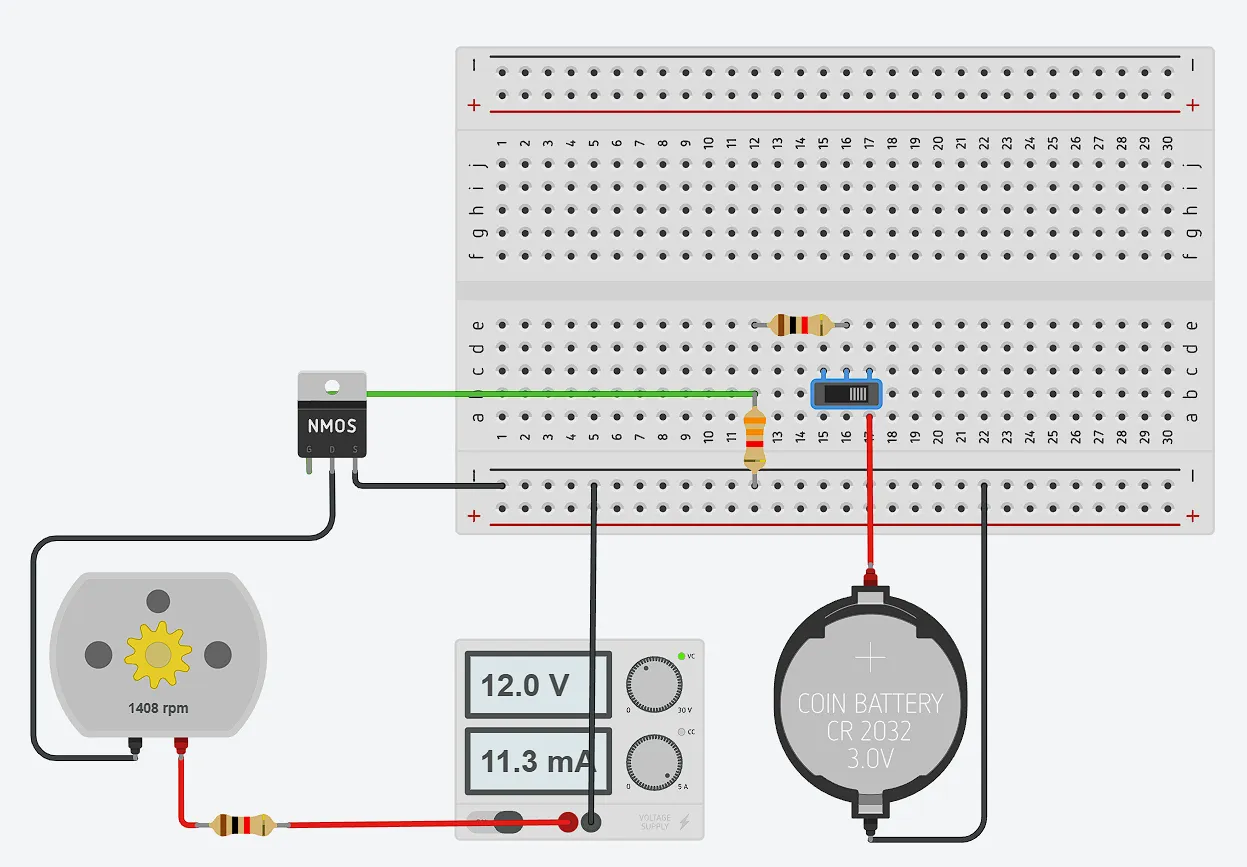
A MOSFET is a switch with three pins and no moving parts. You do not feed it current: you put a voltage on one pin, called the Gate, and the switch closes.
That is why a microcontroller can drive it directly. The MCU supplies a voltage, while a separate supply provides the current. The current enters at the Drain, passes through the load and leaves at the Source.
So the control signal and the load current travel different paths and meet at the Source, which shares the MCU’s ground. That is not isolation: the shared ground is exactly what lets a 3.3V signal control the switch. Real isolation needs an optocoupler or a relay, later in this note.
What the three pins do
| Pin | Name | Role |
|---|---|---|
| G | Gate | Control input, virtually no steady current |
| D | Drain | Connects to load, carries the work current |
| S | Source | Current return (NMOS usually to GND) |
Those three names are the whole vocabulary: you control the Gate, and the Drain-to-Source path does the work.
Why MCUs Can’t Drive Loads Directly
Your 12V panel draws 24W, so 2A. A GPIO offers about 20mA at 3.3V: a hundred times too little, and the wrong voltage.
Wire the panel straight to the pin and the pin cannot hold its level: the voltage sags, the chip heats up. So the job splits in two. The MCU decides when to switch, a separate supply provides the current, and the MOSFET joins them.
NMOS vs PMOS
MOSFETs come in two polarities, and the names only tell you where the switch sits.
NMOS: the switch on the ground side
12V
 │
LED
 │
NMOS
 │
GND
NMOS sits between the load and ground. Its Gate is measured against that same ground, so a 3.3V pin turns it on directly.
PMOS: the switch on the supply side
12V
 │
PMOS
 │
LED
 │
GND
PMOS sits between the supply and the load. Its Gate must be pulled below the supply to turn it on, so it has to rise to nearly 12V, which a 3.3V pin cannot reach. That is why I do not recommend it to begin with.
PWM Dimming
PWM stands for pulse-width modulation. It does not lower the voltage: it switches the load fully on and off, very fast, and varies how long each “on” burst lasts. The average power follows that ratio, so the lamp looks dimmer or brighter.
The switching has to be faster than your eye can follow. Past roughly 200 switches a second an LED looks steady. The Arduino default of about 490 a second is well above that.
Too slow and you see flicker or hear a whine; very fast and the MOSFET spends more of each cycle half-on, which turns into heat.
Why You Need a Freewheeling Diode
This applies to anything built from a coil: motors, fans, solenoids, relay coils.
A coil stores energy in a magnetic field. When the MOSFET switches off, that field collapses and pushes a voltage spike back the other way, several times the supply voltage, which can destroy the MOSFET.
The fix is one diode across the coil. A diode is a one-way valve for current: it blocks the normal direction and opens only for the spike, so the stored energy drains around a safe loop.
An LED is not a coil, so it does not need this.
MOSFET vs BJT (NPN/PNP)
| Property | BJT (NPN/PNP) | MOSFET |
|---|---|---|
| Control method | Current-controlled | Voltage-controlled |
| Input impedance | Low | Extremely high |
| GPIO steady current | Required | Virtually none |
| Heat | Higher | Lower |
| High-freq PWM | Average | Excellent |
| High current | Average | Excellent |
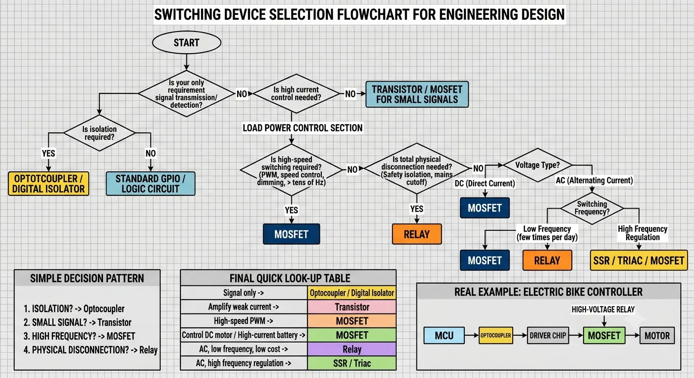
A BJT is the older kind of transistor. It switches on current instead of voltage. You must keep feeding current into one pin, the base, for as long as it should stay on, and that current is wasted as heat. NPN and PNP are its two polarities.
A MOSFET switches on voltage: once its Gate is charged, almost no current flows in, so the MCU holds it on nearly for free. BJTs still suit analog circuits, where their current behaviour is the point.
Relay vs MOSFET
| MOSFET | Relay |
|---|---|
| No mechanical contacts | Mechanical contacts |
| PWM capable | No PWM |
| Fast | Slower |
| Long life | Limited mechanical life |
| Silent | Audible click |
| DC only | AC/DC both |
A relay is a mechanical switch, not a semiconductor: a small coil pulls a metal contact closed. It can switch AC as well as DC, and when it is open there is a real physical gap, so nothing leaks across.
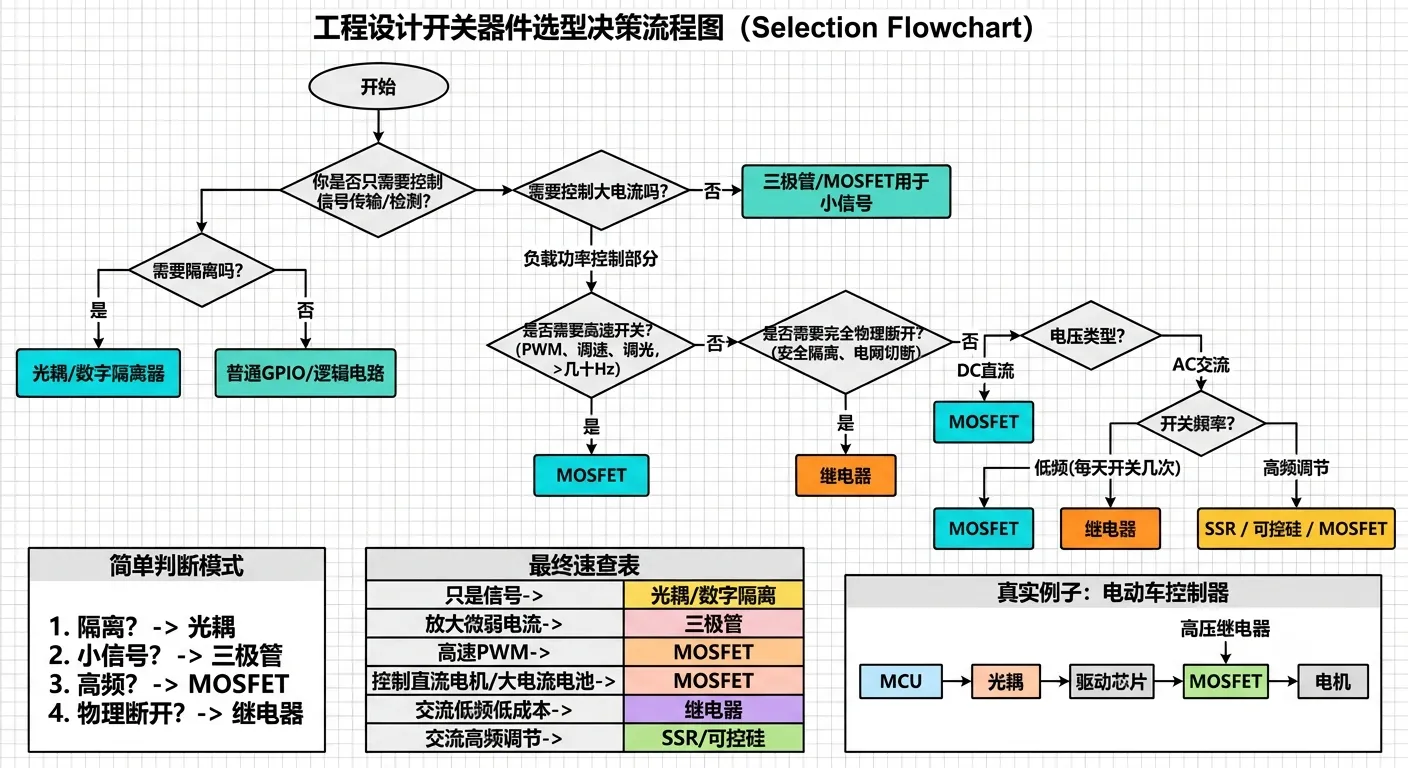
I use a relay for mains AC, for that physical gap, or when the two sides must stay completely separate. I use a MOSFET for DC loads like LEDs, motors and fans, where I want fast, silent PWM switching.
Optocoupler: When You Need True Electrical Isolation
An optocoupler passes a signal as light: inside, a small LED and a light sensor face each other across a gap, so no wire joins the two sides.
That is what makes it safe next to mains voltage: a 3.3V microcontroller can switch mains equipment, and the mains side has no conductive path back into it. It also keeps the two sides from sharing a ground.
The usual chain is: MCU pin, a current-limiting resistor, the optocoupler, the driver stage, and finally the mains load.
Industrial Product Analysis: My Framework
When I open a product and want to understand its power section, this is the order I work in.
- Where does power enter?
- Which parts are the high-power loads?
- What drives them (MOSFET/relay)?
- How does the MCU control them (GPIO/PWM)?
- What protection is in place (freewheeling diode, voltage clamp, fuse, optocoupler)?
LED lamps, RGB strips, fans and pumps all follow this pattern.
Design Notes: Lessons Learned
Choose a MOSFET that turns on fully at 3.3V. Many are built for a 10V control signal and only half-open at 3.3V. A half-open switch acts like a resistor, and a resistor carrying 2A gets hot. The ones you want are sold as “logic-level”.
Never leave the Gate floating. Put a 10kΩ resistor from the Gate to ground. Otherwise the Gate sits at an undefined voltage whenever the MCU is not driving it, and it can turn the switch partly on and burn power for nothing.
Put a small resistor in series with the Gate, 10 to 100Ω. The Gate acts like a small capacitor, so every flip sends a brief surge of current that the resistor keeps off the pin.
Inductive loads must have a freewheeling diode. See above. It is not optional.
Join the grounds. The MCU ground and the supply ground must be connected directly. Without a shared reference the Gate voltage means nothing and the switch never turns on. This is the classic beginner trap. If you need the two sides truly separate, use an optocoupler.
Save these until the basics feel normal:
- Picking a MOSFET means comparing four datasheet numbers: gate threshold, on-resistance, maximum current and maximum voltage.
- For the freewheeling diode, a 1N4148 suits a small relay coil, an SS14 bigger currents.