Article: Purpose and Principles of Pull-Up and Pull-Down Resistors: Zhihu
What a Button Actually Is
After this note you will know why a bare button cannot be read reliably, why one resistor fixes it, and when you still need software on top.
A button is two metal contacts that touch when you press it. The chip that reads it is a microcontroller, or MCU, the small computer running your firmware. The MCU cannot see those contacts move. It can only measure the voltage on one of its pins, and a pin you read is called a GPIO. So: you press, the contacts touch, the pin voltage changes, and the firmware decides what that means.
Two words first. LOW means the pin sits near 0V, the voltage of ground. HIGH means it sits near the supply voltage, 3.3V on most boards and 5V on older ones.
The Floating Problem
The simplest wiring is a pin, a button and ground: GPIO → Button → GND. Press it and the pin connects to ground, so the MCU reads LOW.
The trouble starts when you let go. The pin is now connected to nothing, so nothing holds its voltage. We say the pin floats, and it drifts with nearby electrical noise. Your firmware then sees presses that never happened. The pin needs something to hold it at a known level while the button is open, and that something is a resistor.
A Beginner’s Mistake
It is tempting to wire the pin straight to the supply: 5V → GPIO → Button → GND. While the button is open the pin reads HIGH, which looks right.
Press it, though, and you have connected 5V to ground through nothing but a wire and a switch. Almost no resistance is left in that path, so only the supply itself limits the current. Something there gets hot and fails.
There is a second problem, and it is there before you press anything. 5V on a pin that runs on 3.3V is more than the pin can survive. Every pin has a small protection diode inside that conducts when the voltage goes too high, and it pushes current back into the 3.3V rail.
Never do this.
The Right Way
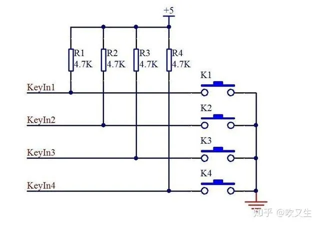
5V → 10kΩ resistor → GPIO + Button → GNDPut a resistor between the supply and the pin instead. A resistor limits how much current can flow, and 10kΩ means 10,000 ohms.
- Not pressed: the resistor connects the pin to 5V, so the pin reads HIGH. The pin draws almost no current, so almost no voltage is lost across the resistor.
- Pressed: the button connects the pin to ground, so the pin reads LOW. The resistor now sets the current: 5V / 10kΩ = 0.5mA, a fraction of what an indicator LED uses. On a 3.3V board the same circuit draws 0.33mA, which is what the rest of this note uses.
The resistor pulls weakly, the button pulls hard. While the button is open the resistor wins and holds the pin HIGH; press it and the direct connection to ground wins easily.
Pull-Up vs Pull-Down
3.3V
│
10kΩ
│
●──── GPIO
│
│
Button closed
│
GND
The resistor can sit on either side of the pin, which gives you the two names:
- Pull-up: resistor from the supply to the pin. Default HIGH, pressed LOW, which is called active-low.
- Pull-down: resistor from the pin to ground. Default LOW, pressed HIGH, which is called active-high.
Both hold a default level, and both limit the current, which is why you never get the dead short from the previous section.
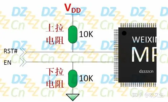
What decides between them is the level your firmware expects. A pin that must not be active at power-up gets a pull-up if it is active-low, a pull-down if it is active-high.
One more case is worth knowing. Some chips can only pull a line low, never high, because the output transistor inside works in one direction only. On those lines the pull-up resistor is the only thing that can produce the HIGH level.
Why Not Wire GPIO Directly to 3.3V?
The same failure as the beginner’s mistake, just at 3.3V: press the button and you connect the supply straight to ground. The resistor is what limits that current.
Why 10kΩ?
A lower resistance holds the pin more firmly and shrugs off noise better, but burns more current. A higher resistance burns less, but noise overrides it more easily. 10kΩ is the usual compromise.
At 3.3V it draws 3.3V / 10kΩ = 0.33mA, small enough to ignore. Read it like this: at a fixed voltage, a bigger resistor means less current.
Which side you pull depends on what the pin does. An enable pin that must stay off at power-up gets a pull-down if it is active-high, and a pull-up if it is active-low: a motor driver, for instance, must not be switched on by noise when its pin floats.
Most MCUs also have a pull-up built in, switched on in software. It is weak, usually tens of kΩ: fine on a short wire, less trustworthy on a long one.
Why Buttons Bounce
Real buttons are not clean switches. Their contacts are pieces of metal that hit each other, so they touch, bounce apart, touch again and finally settle, all within a few milliseconds. Your firmware may run thousands of times in those milliseconds, and every bounce looks like a separate press. One press can be counted as five.
Debounce: Why One Press Can Count as Ten
Debouncing means ignoring that noise, and there are two ways to do it.
Software debounce: when the firmware sees the pin change, it waits about 20ms and reads the pin again. If the pin is still in the new state, the press was real. No hardware cost, and enough for most buttons.
Hardware debounce: a resistor and a capacitor next to the pin smooth the fast jumps out, so the firmware sees only one clean change. The capacitor stores a little charge, which stops the voltage from jumping instantly. Some chips also have a Schmitt trigger input: a circuit that shoves a half-way voltage decisively to one side instead of wobbling.
Most products do both: the capacitor clears the noise, the firmware confirms.
Production-Grade Button Circuit
3.3V
│
10kΩ
│
GPIO────┼────100nF────GND
│
Button
│
GND- Button: user input
- 10kΩ: pull-up, anti-float, current limiting
- 100nF cap: hardware debounce, noise filtering
- GPIO: state detection
What Industrial Designers Should Know
- Mechanical design: button size, travel, actuation force, rebound speed, tolerances, wear.
- Environmental reliability: water and dust (IP rating), ESD, EMC.
- User experience: single click, double click, long press, repeat, feedback (haptic, visual, audio).
- Product lifetime: rated cycles, mechanical fatigue, temperature effects.
A TV remote and a rice cooker use the same button logic: user input → button → GPIO → MCU → execute function.
Core Summary
- Core circuit: 3.3V → pull-up resistor → GPIO node → button → GND.
- Core idea: the resistor provides the default state and limits current, the button changes the circuit, the GPIO reads the result.
FAQ
Why Pull-Up Dominates in Industrial Design
Built-In MCU Pull-Ups Are Free
Most MCUs have a pull-up inside the pin, switched on with one line of code, saving a part and some board space. Pull-downs are less common: many classic 8-bit chips, AVR and 8051 among them, have none at all.
Fail-Safe: What an Open Circuit Actually Does
If the wire to the button breaks, the pull-up pulls the pin back to HIGH, which means not pressed: a broken wire does not look like a press.
Flip the circuit around. A pull-down holds the pin LOW, and in that scheme LOW also means not pressed, so a broken wire fails to idle in both cases.
What differs is a short. With a pull-up, a short to ground reads as a permanent press; with a pull-down, a short to the supply does. In a car, a wire is far more likely to touch the chassis than the supply.
Ground as Reference Is More Reliable
Ground is the 0V reference for the whole board, and its impedance is very low, which makes it stiffer than the supply rail.
Power and Logic Naturally Align
While the button is open no current flows, and while you hold it the current is tiny. A pull-down draws the same current when pressed, so neither side saves power. Many chips also treat a low level as the active one, reset pins for example.
Open-Drain and Bus Compatibility
Some wires are shared by several chips, I²C for instance: no chip drives them high, only low, and one resistor pulls them high for everybody.
When Would You Actually Choose Pull-Down?
- The pin is active-high: some reset and enable pins expect a high level. Wire the button to give HIGH when pressed, which means a pull-down.
- The chip only wakes on a rising edge: some very low-power MCUs only wake when the pin goes from low to high, which forces a pull-down with the button to the supply.
Further Reading
Internal vs External Pull-Up
Use the built-in one while the wire is short and the board is quiet, and add an external 10kΩ when the wire is long or noisy.
Debounce State Machine
Waiting 20ms covers one click. For double clicks and long presses, keep track of where you are:
IDLE → press detected → DEBOUNCE_PRESS (wait 20ms) → PRESSED (act, then watch for release) → release detected → DEBOUNCE_RELEASE (wait 20ms) → back to IDLE.
That structure stops a long press from firing over and over.
Polling vs Interrupt
Polling means the main loop reads the pin every time it goes around: simple, but it keeps the CPU busy.
An interrupt does the opposite. The pin change itself calls a small piece of code, called an interrupt handler, and the CPU can sleep until then, which is why battery-powered devices use it. Many designs do both: the interrupt wakes the system, polling handles the debounce.
Quantitative Hardware Debounce Design
10kΩ and 100nF are the usual starting point, and together they give a 1ms time constant, longer than a single bounce. As a filter the cut-off is 1/(2πRC) ≈ 159Hz: changes slower than about 160 times a second get through, faster ones are smoothed away.
Safety and Reliability Design
If the firmware ever sets the pin as an output by mistake, pressing the button shorts it to ground. A 100Ω to 1kΩ resistor in series with the button limits the fault current (3.3V / 100Ω = 33mA). Check your chip’s per-pin limit before using the low end, because some chips allow less.
An exposed button is also a path for static from your finger; a protection diode to ground gives it somewhere to go before it reaches the chip.
Multi-Button and GPIO Optimization
One pin per button runs out quickly. The usual answers are a matrix, where buttons share rows and columns, or a resistor ladder, where one pin reads a different voltage per button.